Operational Amplifiers
Explanations of the pin numbers are below:

1. You will use the OPAMP in “open-loop” configuration in this part, where input signals will be applied directly to the pins 2 and 3.
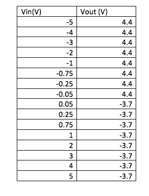
a. Apply 0 V to the inverting input. Sweep the non-inverting input (Vin) from -5 V to 5 V with 1 V steps. Take more steps around 0 V (both positive and negative). Create a table for Vin and Vout. Plot the data (Vout vs Vin). Discuss your results. What would be the ideal plot?
In this experiment, we applied a voltage from -5V (lowest value) to 5V(highest value) in an open loop configuration. When we applied the smallest value, we got the maximum output and that because in an open loop configuration, there is no resistors to reduce the operational amplifier effect which means that the maximum value will be reached even if we apply a small value. Also, the OpAmp has a very large gain and because of that the output will be large but because we applied a voltage value between -5V and 5V, our outputs will not be larger than 5V. Our maximum value was -3.7V and 4.4V as it is shown in the table.
 | ||
|
 | |
|
We applied a -5V and 5V to investing input and the output results were the same value but they were opposite signs as it is shown in the table. The maximum values were the same as the non-inverting input with different sign, for the - input the maximum value was 4.4V and for the + input the maximum value was -3.7V which is the opposite.
 | |
|

| Graph1.2: shows operational amplifier-sweeping inverting input |
 |
| graph2.1: Non inverting amplifier |
 |
| Table2.1:shows the measured and calculated output of a Non-inverting amplifier |
3. Create an inverting amplifier. (Rf = 2 kΩ, Rin = 1 kΩ). Sweep Vin from -5 V to 5 V with 1 V steps. Create a table for Vin and Vout. Plot the measured and calculated data together.
 |
| graph3.1: inverting amplifier |
 |
| Table3.1:souls the measured and calculated output of an inverting amplifier |
4. Explain how an OPAMP works. How come is the gain of the OPAMP in the open loop configuration too high but inverting/non-inverting amplifier configurations provide such a small gain?
The Operation amplifier increases the the amplitude of the input signal and then the output signal will be larger by the gain factor. The gain in an open loop configuration is too high because it doesn't have any resistors which means the minimum value of input can reach the maximum output easily. However, for the inverting/non inverting amplifier configuration, they provide a small gain because the gain is the ratio between the two resistors which means there gain will depend on the value of the resistors and there output will be the the input multiplied by the gain factor.
EGR 393 Temperature Controlled LED System
Tips:
1. If something is not working, check your connection first.
2. Check the pins carefully, LM35 is VERY easy to be burned if you connect the wrong pins.
3. Read the datasheet carefully.
4. Before starting to connect the circuit, try to sketch it on a paper first, make sure everything is clear.
Components:
1. TMP36 Temperature Sensor 2. Lm324 Operational Amplifier 3. OMRON G8QN Relay 4. LED
Procedure:
 TMP36 Temperature Sensor: Pin layout – look up characteristics to calculate temperature from datasheet (under Bb/Week6).
Temperature Sensor: Put TMP36 temp sensor on breadboard.
* Connect the +VS to 5 volts and GND to ground.
* Using a voltage meter, measure the output voltage from the VOUT. Now put your finger (or cover the sensor with your palm) on the TMP36 temperature sensor for a while, observing how the output voltage changes. Check Fig. 6 in the data sheet (EXPLAIN).
Relay (Manual under Bb/Week6)

Pin 1 – Input voltage (amount of voltage sent to pins 3 or 4)
Pin 2 – Power supply
Pin 3 – Vout = Vin when Vin > Vthreshold
Pin 4 – Vout = Vin when Vin < Vthreshold
Pin 5 - GND
schematic view is the bottom view!
1. Connect your DC power supply to pin 2 and ground pin 5. Set your power supply to 0V. Switch your multimeter to measure the resistance mode; use your multimeter to measure the resistance between pin 4 and pin 1. Do the same measurement between pin 3 and pin 1. Explain your findings (EXPLAIN).
Pin 3 to 1 is 1.5 ohms pin 4 to 1 is read as overloaded, but it is because there is noting to read there. The relay is only sending voltage and current to pin 3 not pin 4.
2. Now sweep your DC power supply from 0V to 8V and back to 0V. What do you observe at the multimeter (resistance measurements similar to #1)? Did you hear a clicking sound? How many times? What is the “threshold voltage values” that cause the “switching?” (EXPLAIN with a VIDEO).
Click happened twice. Click happened around 6v on the way to 8v then on the way back to 0 at 2v
3. How does the relay work? Apply a separate DC voltage of 5 V to pin 1. Check the voltage value of pin 3 and pin 4 (each with respect to ground) while switching the relay (EXPLAIN with a VIDEO).
When the power supply is set at 0 before the switch that occurs at 6 v pin 3 reads a 5.02v and pin 4 reads a very small value of volts. After it clicks the the values for the pins switch pin 4 reads 5.02v and pin 3 reads a small voltage. They switch again at the 2v click.
1. Connect positive end of the LED diode to the pin 3 of the relay and negative end to a 100 ohm resistor. Ground the other end of the resistor. Negative end of the diode will be the shorter wire.
2. Apply 3 V to pin 1
3. Turn LED on/off by switching the relay. Explain your results in the video. Draw the circuit schematic (VIDEO)
Operational Amplifier (data sheet under Bb/week 6)
1. Connect the power supplies to the op-amp (+10V and 0V). Show the operation of LM 124 operational amplifier in DC mode with a non-inverting amplifier configuration. Choose any opamp in the IC. Method: Use several R1 and R2 configurations and change your input voltage (voltages between 0 and 10V) and record your output voltage. (EXPLAIN with a TABLE)
2. Use your temperature sensor as your input. Do you think you can generate enough voltage to trigger the relay? (EXPLAIN)
The temperature sensor has too much resistance so if we used hair dryer to heat it up, it wouldn't be enough heat to trigger the relay. Moreover, The temperature sensor needs a source with a really significant heat that would generate enough voltage to trigger the rely. We think if we used temperature sensor with the OpAmp would generate enough voltage to trigger the relay.
3. Design a system where LED light turns on when you heat up the temperature sensor. (CIRCUIT schematic and explanation in a VIDEO)
4. BONUS! Show the operation of the entire circuit. (VIDEO)

The Operation amplifier increases the the amplitude of the input signal and then the output signal will be larger by the gain factor. The gain in an open loop configuration is too high because it doesn't have any resistors which means the minimum value of input can reach the maximum output easily. However, for the inverting/non inverting amplifier configuration, they provide a small gain because the gain is the ratio between the two resistors which means there gain will depend on the value of the resistors and there output will be the the input multiplied by the gain factor.
EGR 393 Temperature Controlled LED System
Tips:
1. If something is not working, check your connection first.
2. Check the pins carefully, LM35 is VERY easy to be burned if you connect the wrong pins.
3. Read the datasheet carefully.
4. Before starting to connect the circuit, try to sketch it on a paper first, make sure everything is clear.
Components:
1. TMP36 Temperature Sensor 2. Lm324 Operational Amplifier 3. OMRON G8QN Relay 4. LED
Procedure:

Temperature Sensor: Put TMP36 temp sensor on breadboard.
* Connect the +VS to 5 volts and GND to ground.
* Using a voltage meter, measure the output voltage from the VOUT. Now put your finger (or cover the sensor with your palm) on the TMP36 temperature sensor for a while, observing how the output voltage changes. Check Fig. 6 in the data sheet (EXPLAIN).
Relay (Manual under Bb/Week6)

Pin 1 – Input voltage (amount of voltage sent to pins 3 or 4)
Pin 2 – Power supply
Pin 3 – Vout = Vin when Vin > Vthreshold
Pin 4 – Vout = Vin when Vin < Vthreshold
Pin 5 - GND
schematic view is the bottom view!
1. Connect your DC power supply to pin 2 and ground pin 5. Set your power supply to 0V. Switch your multimeter to measure the resistance mode; use your multimeter to measure the resistance between pin 4 and pin 1. Do the same measurement between pin 3 and pin 1. Explain your findings (EXPLAIN).
Pin 3 to 1 is 1.5 ohms pin 4 to 1 is read as overloaded, but it is because there is noting to read there. The relay is only sending voltage and current to pin 3 not pin 4.
2. Now sweep your DC power supply from 0V to 8V and back to 0V. What do you observe at the multimeter (resistance measurements similar to #1)? Did you hear a clicking sound? How many times? What is the “threshold voltage values” that cause the “switching?” (EXPLAIN with a VIDEO).
Click happened twice. Click happened around 6v on the way to 8v then on the way back to 0 at 2v
Video 1 shows when the click happens
3. How does the relay work? Apply a separate DC voltage of 5 V to pin 1. Check the voltage value of pin 3 and pin 4 (each with respect to ground) while switching the relay (EXPLAIN with a VIDEO).
When the power supply is set at 0 before the switch that occurs at 6 v pin 3 reads a 5.02v and pin 4 reads a very small value of volts. After it clicks the the values for the pins switch pin 4 reads 5.02v and pin 3 reads a small voltage. They switch again at the 2v click.
Video 2 explain what happens when the click occurs
LED + Relay1. Connect positive end of the LED diode to the pin 3 of the relay and negative end to a 100 ohm resistor. Ground the other end of the resistor. Negative end of the diode will be the shorter wire.
2. Apply 3 V to pin 1
3. Turn LED on/off by switching the relay. Explain your results in the video. Draw the circuit schematic (VIDEO)
 |
| Picture 1 circuit schematic of the LED/Relay circuit |
Video 3 show how to turn an LED light on/off
Operational Amplifier (data sheet under Bb/week 6)
1. Connect the power supplies to the op-amp (+10V and 0V). Show the operation of LM 124 operational amplifier in DC mode with a non-inverting amplifier configuration. Choose any opamp in the IC. Method: Use several R1 and R2 configurations and change your input voltage (voltages between 0 and 10V) and record your output voltage. (EXPLAIN with a TABLE)
 |
| Table 1.1 values of Vin and Vout from opamp with resistors 1 k ohms and 2 k ohms |
 |
| Table 1.2 values of Vin and Vout from opamp with resistors 2 k ohms and 100 ohms |
2. Use your temperature sensor as your input. Do you think you can generate enough voltage to trigger the relay? (EXPLAIN)
The temperature sensor has too much resistance so if we used hair dryer to heat it up, it wouldn't be enough heat to trigger the relay. Moreover, The temperature sensor needs a source with a really significant heat that would generate enough voltage to trigger the rely. We think if we used temperature sensor with the OpAmp would generate enough voltage to trigger the relay.
3. Design a system where LED light turns on when you heat up the temperature sensor. (CIRCUIT schematic and explanation in a VIDEO)
 |
| Picture 3.1 Circuit Schematic |
Video 3.1 explanation of the Circuit Schematic and how the Circuit works.
4. BONUS! Show the operation of the entire circuit. (VIDEO)


